

How Many Bits Does A Register Have In Arm Processor
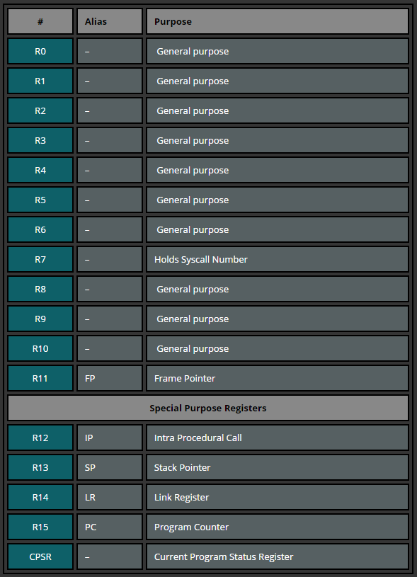
The amount of registers depends on the ARM version. According to the ARM Reference Manual, in that location are 30 general-purpose 32-bit registers, with the exception of ARMv6-M and ARMv7-Grand based processors. The first xvi registers are accessible in user-level fashion, the additional registers are available in privileged software execution (with the exception of ARMv6-M and ARMv7-One thousand). In this tutorial serial nosotros will work with the registers that are attainable in whatever privilege mode: r0-fifteen. These 16 registers can be dissever into two groups: general purpose and special purpose registers.
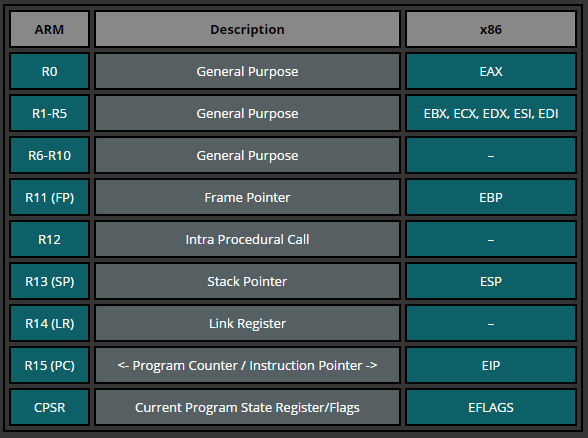
The post-obit table is just a quick glimpse into how the ARM registers could relate to those in Intel processors.
R0-R12: tin can exist used during mutual operations to store temporary values, pointers (locations to retentivity), etc. R0, for example, can be referred as accumulator during the arithmetics operations or for storing the result of a previously called function. R7 becomes useful while working with syscalls equally it stores the syscall number and R11 helps us to go on rail of boundaries on the stack serving every bit the frame arrow (will exist covered later). Moreover, the function calling convention on ARM specifies that the first iv arguments of a function are stored in the registers r0-r3.
R13: SP (Stack Pointer). The Stack Arrow points to the pinnacle of the stack. The stack is an expanse of memory used for office-specific storage, which is reclaimed when the role returns. The stack pointer is therefore used for allocating space on the stack, by subtracting the value (in bytes) we want to allocate from the stack pointer. In other words, if we want to allocate a 32 bit value, we subtract iv from the stack pointer.
R14: LR (Link Register). When a office call is made, the Link Register gets updated with a memory address referencing the side by side pedagogy where the function was initiated from. Doing this allows the program return to the "parent" role that initiated the "child" function telephone call afterward the "child" part is finished.
R15: PC (Plan Counter). The Program Counter is automatically incremented by the size of the instruction executed. This size is e'er 4 bytes in ARM land and 2 bytes in THUMB fashion. When a branch instruction is being executed, the PC holds the destination address. During execution, PC stores the accost of the current instruction plus eight (two ARM instructions) in ARM land, and the current instruction plus 4 (two Thumb instructions) in Thumb(v1) state. This is different from x86 where PC always points to the next instruction to be executed.
Let's expect at how PC behaves in a debugger. We utilise the following programme to store the address of pc into r0 and include two random instructions. Let's see what happens.
.section .text .global _start _start: mov r0, pc mov r1, #ii add r2, r1, r1 bkpt
In GDB we set a breakpoint at _start and run information technology:
gef> br _start Breakpoint 1 at 0x8054 global environment facility> run
Here is a screenshot of the output we see kickoff:
$r0 0x00000000 $r1 0x00000000 $r2 0x00000000 $r3 0x00000000 $r4 0x00000000 $r5 0x00000000 $r6 0x00000000 $r7 0x00000000 $r8 0x00000000 $r9 0x00000000 $r10 0x00000000 $r11 0x00000000 $r12 0x00000000 $sp 0xbefff7e0 $lr 0x00000000 $pc 0x00008054 $cpsr 0x00000010 0x8054 <_start> mov r0, pc <- $pc 0x8058 <_start+4> mov r0, #2 0x805c <_start+8> add together r1, r0, r0 0x8060 <_start+12> bkpt 0x0000 0x8064 andeq r1, r0, r1, asr #x 0x8068 cmnvs r5, r0, lsl #2 0x806c tsteq r0, r2, ror #18 0x8070 andeq r0, r0, r11 0x8074 tsteq r8, r6, lsl #6
Nosotros tin can see that PC holds the accost (0x8054) of the next teaching (mov r0, pc) that will exist executed. At present let'southward execute the side by side instruction after which R0 should concord the address of PC (0x8054), right?
$r0 0x0000805c $r1 0x00000000 $r2 0x00000000 $r3 0x00000000 $r4 0x00000000 $r5 0x00000000 $r6 0x00000000 $r7 0x00000000 $r8 0x00000000 $r9 0x00000000 $r10 0x00000000 $r11 0x00000000 $r12 0x00000000 $sp 0xbefff7e0 $lr 0x00000000 $pc 0x00008058 $cpsr 0x00000010 0x8058 <_start+4> mov r0, #2 <- $pc 0x805c <_start+8> add together r1, r0, r0 0x8060 <_start+12> bkpt 0x0000 0x8064 andeq r1, r0, r1, asr #10 0x8068 cmnvs r5, r0, lsl #two 0x806c tsteq r0, r2, ror #xviii 0x8070 andeq r0, r0, r11 0x8074 tsteq r8, r6, lsl #half-dozen 0x8078 adfcssp f0, f0, #4.0
…right? Wrong. Await at the address in R0. While nosotros expected R0 to contain the previously read PC value (0x8054) information technology instead holds the value which is ii instructions alee of the PC nosotros previously read (0x805c). From this example you can see that when we straight read PC it follows the definition that PC points to the next instruction; but when debugging, PC points two instructions ahead of the current PC value (0x8054 + 8 = 0x805C). This is considering older ARM processors always fetched two instructions ahead of the currently executed instructions. The reason ARM retains this definition is to ensure compatibility with before processors.

How Many Bits Does A Register Have In Arm Processor,
Source: https://azeria-labs.com/arm-data-types-and-registers-part-2/
Posted by: jenningsramord94.blogspot.com
0 Response to "How Many Bits Does A Register Have In Arm Processor"
Post a Comment